Objectif :
1//Contrôler en temps réel le plotter.
2//Imaginer un dictionnaire de formes et une télécommande pour communiquer avec le plotter.
Liens :
//Contrôler le plotter XY avec le clavier
https://github.com/Makeblock-official/XY-Plotter-2.0/blob/master/README.md?fbclid=IwAR15tn0Z3Ai9YmRqixUBdEZqjNMVzuetJ4goVZEmashMjc70v4TEV1-93bM
//Vidéo contrôle d’une CNC avec un clavier télécommande
//Branchements de la “me baseboard” (user guide)
https://www.makeblock.com/project/xy-plotter-robot-kit
Projets et avancement :
A/ Controle du plotter par ordinateur et Arduino Uno
![]() Partie I : Contrôle du plotter
Partie I : Contrôle du plotter

![]()
Les moteurs XY sont branchés à une carte Arduino via un CNC shield. Un code GRBL est envoyé dans l’Arduino ce qui permet de piloter les moteurs via un logiciel type G-code sender, GRBL Controller, Panneau de contrôle GRBL, ainsi que de lui envoyer un fichier G-Code.
Lien de téléchargement de Panneau de contrôle GRBL :
Lien de téléchargement du code GRBL :
Partie II : Contrôle du servo Axe Z

Code Arduino pour le servo moteur :
Afin que la manipulation du servo fonctionne il ne faut PAS aller dans Fichier > Exemple MAIS dans Croquis > Inclure une bibliothèque > “le fichier correspondant au servo”
#include <Servo.h> //accesses the Arduino Servo LibraryServo myservo; // creates servo object to control a servo
int val; // variable to read the value from the analog pin
void setup()
{
myservo.attach(6); // ensures output to servo on pin 9
}
void loop()
{
val = analogRead(3); // reads the value of the potentiometer from A1 (value between 0 and 1023)
val = map(val, 0, 1023, 0, 90); // converts reading from potentiometer to an output value in degrees of rotation that the servo can understand
myservo.write(val); // sets the servo position according to the input from the potentiometer
delay(15); // waits 15ms for the servo to get to set position
}
Partie III : Générer le G-code via Illustrator
On utilise ensuite un plug-in d’illustrator qui permet de générer un G-code à partir d’un fichier Illustrator.
Lien de téléchargement du plug-in pour Illustrator :
https://diegomonzon.com/illustrator-to-gcode/
Copier-coller ensuite le fichier télécharger à l’emplacement suivant :
Pour une version CS6 d’illustrator:
(C:) > Programmes > Adobe > Adobe Illustrator CS6 (64 Bit) > Paramètres prédéfinis > fr_FR > Scripts
Pour une version CC d’illustrator :
(C:) > Programmes >Adobe > Adobe Illustrator CC ( “année de version” ) > Support Files > Content > Windows > Scripts
Partie IV : Utilisation du panneau de contrôle GRBL
Une fois le G-code générer grâce au plug-in d’illustrator il est possible de visualiser le code grâce au logiciel Notepad++ et de le modifier.
Lien de téléchargement de Notepad ++
>>>> Par défaut le plug-in fera un G-code avec une ligne ” G4 P500″ qui signifie que le plotter fera une pause entre chaque action, afin de résoudre ce problème il suffit d’aller chercher le fichier du plug-in , précédement installer dans le répertoir convenant à votre version d’illustrator. Ensuite ouvrez le fichier .jsx avec Notepad ++. Faites Ctrl + H , une fenetre s’ouvre , dans “Recherche” tapez ” G4 P500″ puis dans ” Remplacer par” , tapez “G4 P0”.
Ainsi vous n’aurez pas de pause entre chaque action de déplacement du plotter.
Lien pour la liste des commande GRBL :
https://shapeoko.com/wiki/index.php/G-Code
Tuto utilisation GRBL Panel :
Dans le Panneau de contrôle GRBL dans l’onglet réglages il faut les valeurs $100 et $101 sur 55 step/mm afin qu’une « unité de distance » corresponde à 1 cm. La machine ne pouvant pas fonctionner en mm on est obligé de travailler en cm.
1mm sur Illustrator = 1cm sur le papier
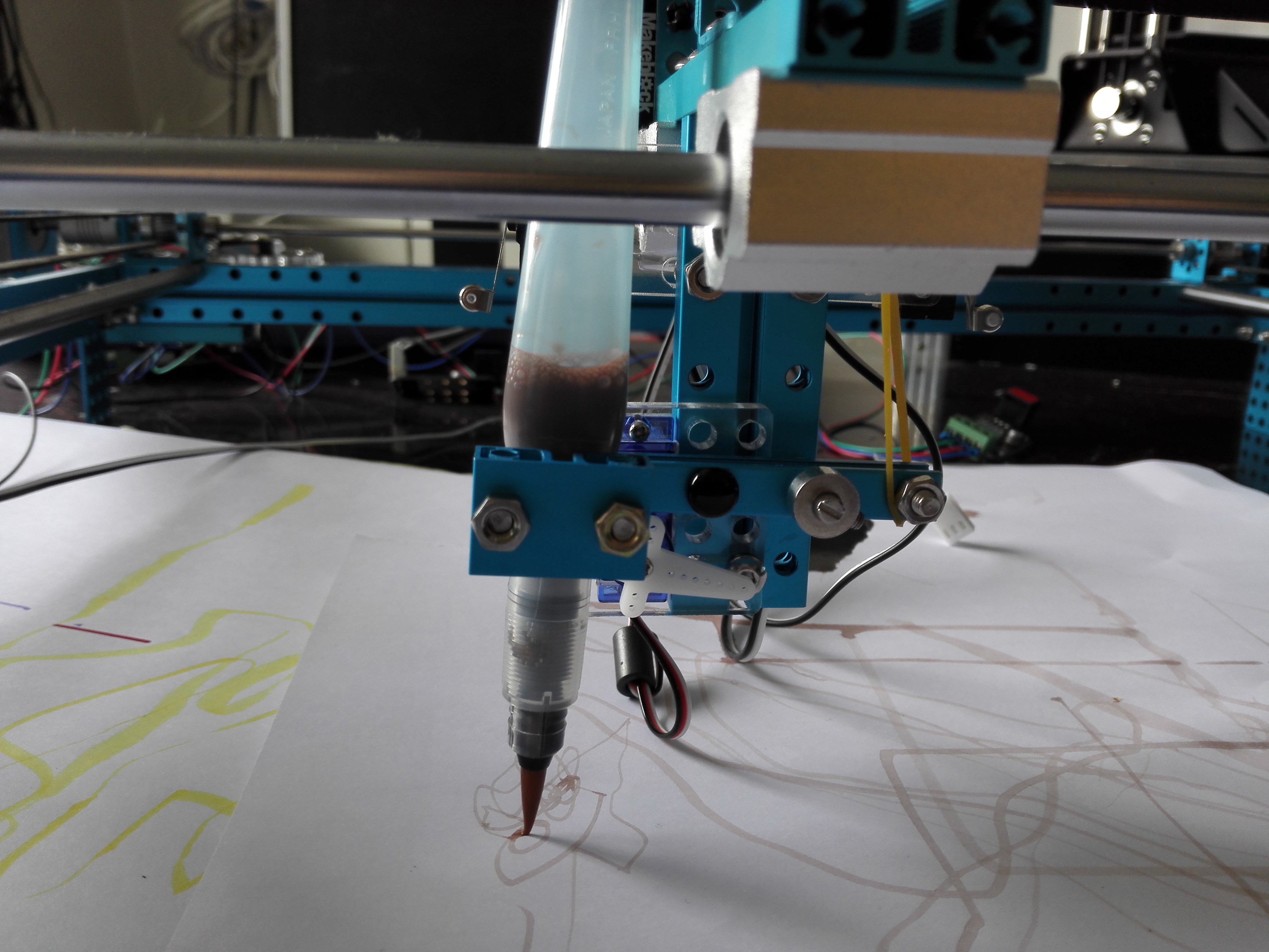
Voici des exemple de fonctionnement :
Et voici quelques dessins test réalisés :


B/ Contrôle du plotter par l’utilisation d’un joystick et d’un potentiomètre
Matériel nécessaire :
-Un joystick deux axe XY
-Une Arduino UnO
-Un potentiomètre
-Deux Driver Stepper motor ( Easy Driver)
Pour prendre le contrôle du plotter via un joysiock deux axe ( XY) il faut un driver par axe ou un driver pouvant gérer deux axe a la fois.
Exemple d’un driver ( EasyDriver V4.4) pour un seul axe:

Ensuite il faut réaliser le branchement suivant :
Vu qu’il y’a deux driver il faut faire deux fois le meme branchement avec les ports (PWM ) > ~2 ~3 ~5 ~6 ~7 ~8 ~9 ~10 ~11 ~12
Partie I : Contrôle via le Joystick deux axe
Afin de contrôler le plotter par le Joystick il faudra implémenter le code suivant dans la carte Arduino :
//Declare pin functions on Redboard

//Y
#define stp1 2
#define dir1 3
#define MS1 5
#define MS2 6
#define EN1 7
//X
#define stp2 8
#define dir2 9
#define MS3 10
#define MS4 11
#define EN2 12
//Declare variables for functions
char user_input;
int y;
int x;
int state1;
int state2;
int joyX = A0;
int joyVal2;
int joyY = A2;
int joyVal1;
int delayTime = 3000;
void setup() {
//Y
pinMode(stp1, OUTPUT);
pinMode(dir1, OUTPUT);
pinMode(MS1, OUTPUT);
pinMode(MS2, OUTPUT);
pinMode(EN1, OUTPUT);
//X
pinMode(stp2, OUTPUT);
pinMode(dir2, OUTPUT);
pinMode(MS3, OUTPUT);
pinMode(MS4, OUTPUT);
pinMode(EN2, OUTPUT);
//Y
digitalWrite(stp1, LOW);
digitalWrite(dir1, LOW);
digitalWrite(MS1, LOW);
digitalWrite(MS2, LOW);
digitalWrite(EN1, HIGH);
//X
digitalWrite(stp2, LOW);
digitalWrite(dir2, LOW);
digitalWrite(MS3, LOW);
digitalWrite(MS4, LOW);
digitalWrite(EN2, HIGH);
Serial.begin(9600); //Open Serial connection for debugging
}
//Main loop
void loop() {
// while loop Y
if (true) {
Serial.print(” Y = “);
Serial.print(analogRead(A0));
Serial.print(“\t X = “);
Serial.println(analogRead(A2));
}
while ( (analogRead(joyY) < 400 ) || (analogRead(joyY) > 600 ) || (analogRead(joyX) < 400 ) || (analogRead(joyX) > 600 )) {
joyVal1 = analogRead(joyY);
joyVal2 = analogRead(joyX);
digitalWrite(EN1, LOW);
digitalWrite(EN2, LOW);
if ( joyVal1 < 400) {
digitalWrite(dir1, LOW);
}
else if ( joyVal1 > 600) {
digitalWrite(dir1, HIGH);
}
if ( joyVal2 < 400) {
digitalWrite(dir2, LOW);
}
else if ( joyVal2 > 600) {
digitalWrite(dir2, HIGH);
}
if (joyVal1 < 400 || joyVal1 > 600) {
digitalWrite(stp1, HIGH); //Trigger one step forward
digitalWrite(stp1, LOW); //Pull step pin low so it can be triggered again
}
if (joyVal2 < 400 || joyVal2 > 600) {
digitalWrite(stp2, HIGH); //Trigger one step forward
digitalWrite(stp2, LOW); //Pull step pin low so it can be triggered again
}
delayMicroseconds(delayTime);
}
}
#include <Servo.h> //accesses the Arduino Servo Library
Servo myservo; // creates servo object to control a servo
int val; // variable to read the value from the analog pin
void setup()
{
myservo.attach(6); // ensures output to servo on pin 9
}
void loop()
{
val = analogRead(4); // reads the value of the potentiometer from A1 (value between 0 and 1023)
val = map(val, 0, 1023, 0, 90); // converts reading from potentiometer to an output value in degrees of rotation that the servo can understand
myservo.write(val); // sets the servo position according to the input from the potentiometer
delay(15); // waits 15ms for the servo to get to set position
Il faut bien vérifier que les branchements des moteur sur la Carte Arduino soient fait sur des ports PWM ( ex: ~3)
Partie II : Contrôle du servo moteur pour l’axe Z
Afin de controler le servo moteur il faut le brancher sur un GND , un +5V ainsi qu’un port PWM.
Dans notre cas, travaillant sur une Arduino Uno nous n’avons pas pu brancher le sevo moteur sur la même carte Arduino et utilisation d’une deuxième carte fut nécessaire.
Vidéo Tuto du branchement du potentiomètre sur l’Arduino :
https://www.instructables.com/id/Arduino-How-to-Control-Servo-Motor-With-Potentiome/
Sur la deuxieme carte Arduino ( controllant le servo via le potentiometre) nous avons implementer le code suivant :
#include <Servo.h> //accesses the Arduino Servo LibraryServo myservo; // creates servo object to control a servo
int val; // variable to read the value from the analog pin
void setup()
{
myservo.attach(6); // ensures output to servo on pin 9
}
void loop()
{
val = analogRead(3); // reads the value of the potentiometer from A1 (value between 0 and 1023)
val = map(val, 0, 1023, 0, 90); // converts reading from potentiometer to an output value in degrees of rotation that the servo can understand
myservo.write(val); // sets the servo position according to the input from the potentiometer
delay(15); // waits 15ms for the servo to get to set position
}
Cependant nous n’avons pas réussi a pendre le contrôle parfait du joystick et du potentiomètre afin de réaliser des courbes :